True Position Calculator
|
| Feature Type:
|
|
|
|
|
|
|
|
|
|
|
|
|
|
|
|
|
|
|
|
|
| Results are synced with controls: No |
| |
| Feature within Tolerance: |
No
|
| Feature within position: |
No
|
| Tolerance Bonus: |
|
| Actual True Position: |
|
| |
| Projection height: |
|
|
| Projection height: |
|
| Projection within position: |
No
|
| Projection True Position: |
|
| Distance to Datum B: |
|
| Distance to Datum C: |
|
| |
|
| Feature within Tolerance: |
No
|
| Feature within position: |
No
|
| Tolerance Bonus: |
|
| Actual True Position: |
|
| |
|
| Actual True Position: |
|
| A Tolerance Bonus: |
|
| Feature within position: |
No
|
| Feature within Tolerance: |
No
|
|
|
| Projection height: |
|
| Projection within position: |
No
|
| Projection True Position: |
|
| Projection Distance to Datum B: |
|
| Projection Distance to Datum C: |
|
| |
|
| Feature within Tolerance: |
No
|
| Feature within position: |
No
|
| Tolerance Bonus: |
|
| Actual True Position: |
|
| Distance to Datum B: |
|
| Distance to Datum C: |
|
|
| |
| Distance to Datum B: |
|
| Distance to Datum C: |
|
| Actual True Position: |
|
| Tolerance Bonus: |
|
| Feature within position: |
No
|
| Feature within Tolerance: |
No
|
|
|
version (beta) 0.9.0
THE SOFTWARE IS PROVIDED "AS IS" AND THE AUTHOR DISCLAIMS ALL WARRANTIES WITH REGARD TO THIS SOFTWARE INCLUDING ALL IMPLIED WARRANTIES OF MERCHANTABILITY AND FITNESS. IN NO EVENT SHALL THE AUTHOR BE LIABLE FOR ANY SPECIAL, DIRECT, INDIRECT, OR CONSEQUENTIAL DAMAGES OR ANY DAMAGES WHATSOEVER RESULTING FROM LOSS OF USE, DATA OR PROFITS, WHETHER IN AN ACTION OF CONTRACT, NEGLIGENCE OR OTHER TORTIOUS ACTION, ARISING OUT OF OR IN CONNECTION WITH THE USE OR PERFORMANCE OF THIS SOFTWARE.
Description:
NOTE: The calculator is incomplete and additional features will be added later on. Please report any bugs or erroneous results here. Thank you.
The true position calculator is a tool to calculate the true position of the center axis after actual measured dimensional data is entered about a manufactured feature: either a hole or a shaft. It is compared to a theoretically exact target feature as described on a technical drawing document.
Please note that not all possible combination of control frame features are supported by this calculator.
The position control frame found on technical drawing documents are used to allocate an acceptable deviation to a hole or a shaft feature.
One basic function of the true position tolerance is to prevent a component from forcing another component out of alignment at assembly time. It takes into consideration the allowable deviation of sizes of the relevant features of an assembly. For example: a screw that binds multiple components together.
The position control frame can also be seen as a way to ensure exact positioning, within acceptable deviation limits, of multiple components of an assembly. For example; dowel pins that slide into positioning holes.
Recommended Usage Flow:
- Select the type of feature; hole or shaft.
- Define the feature diameter basic size and deviation.
- Fill control frame data, positional diameter, boundary condition, whether the target is projected and the projected distance.
- Define the primary, secondary and tertiary datum plane label identifiers.
- Enter the target distances of the feature to the secondary and tertiary datum planes.
- Select the type of measurement type that is most appropriate.
- Enter the measured dimensional data.
- Compute all the data entered and evaluate results.
Target Feature Box
Measurements Box
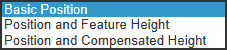
This is the where the actual measured size and position dimensions of the feature are entered. There are 3 ways to describe the actual size and position of the manufactured feature.
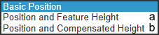
- 1- Basic position:
- - NOTE: All the dimensions are located on the primary datum plane.
-
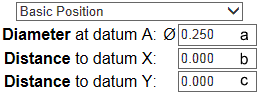 a) The actual diameter of the feature
b) The actual distance of the center of the feature to the secondary datum plane
c) The actual distance of the center of the feature to the tertiary datum plane
- - NOTE: The projected distance is not considered.
- 2- Position and feature height
-
- 2 sets of dimensions must be entered. The first set of measurements must be taken at the primary datum plane. The second set of dimension must be taken AT the "feature height" distance from the primary datum.
-
a) Feature height:
The distance that the second set of measurements will be taken, and positional calculations will be applied or from which the calculated projected position will be evaluated.
-
Measurements located on the primary datum plane. (Datum data)
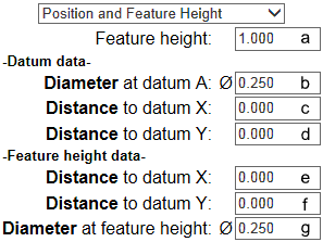
- b) The actual diameter of the feature
- c) The actual distance of the center of the feature to the secondary datum plane
- d) The actual distance of the center of the feature to the tertiary datum plane
-
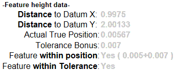
Measurements located at the "feature height" FROM the primary datum plane (Feature height data)
- e) The actual distance of the center of the feature to the secondary datum plane
- f) The actual distance of the center of the feature to the tertiary datum plane
- g) The actual diameter of the feature
- 3- Position and Compensated Height
-
- This set of measurements is to be used when the feature cannot be measured at the primary datum plane or at the "feature height" distance from the primary datum plane.
-
- 2 sets of dimensions must be entered. The first set of measurements must be taken NEAR the primary datum plane. The second set of dimension must be taken NEAR the "feature height" distance from the primary datum.
-
a) Feature height:
The distance that the second set of measurements will be EVALUATED, and positional calculations will be applied or from which the calculated projected position will be evaluated.
-
- Measurements located NEAR the primary datum plane. (Datum data)
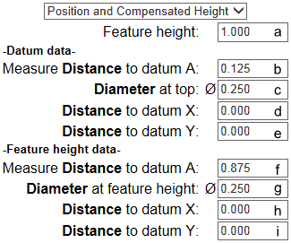
- b) The distance from the PRIMARY datum plane the measurements are taken
- c) The actual diameter of the feature
- d) The actual distance of the center of the feature to the secondary datum plane
- e) The actual distance of the center of the feature to the tertiary datum plane
-
- Measurements located NEAR the "feature height" FROM the PRIMARY datum plane (Feature height data)
- f) The distance from the PRIMARY datum plane the measurements are taken
- g) The actual diameter of the feature
- h) The actual distance of the center of the feature to the secondary datum plane
- i) The actual distance of the center of the feature to the tertiary datum plane
Results Box
This is where all the calculated results are displayed. They are filtered depending on a combination of the target control frame inputs and the type of measurements entered.
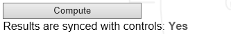
- Compute button:
-
- Evaluate entered data and update results.
-
Results are synced with controls: Yes/No
-
( IMPORTANT information )
-
- This gives a feedback on the state if the results that are showed.
-
- If the result displays a "Yes". This means that the calculated values displayed were calculated using the unmodified values in the input fields above.
-
- If the result displays a "No". This means that the values in the input fields were modified. The results displayed shows values that were calculated using a prior set of input values.
-
NOTE Projected position are only evaluated if the type of measurements input entered are...
-
 a) Position and Feature Height
b) Position and Compensated Height
- The results are summarized in three different value sets.
- - Datum data ( this set of values is always displayed .)
- - Feature height data ( this set of values is not always displayed and can appear grayed out, and in such a case, are for reference only.)
- - Projected data ( this set of values only appears when a projected distance is selected in the target control frame.)
- -Datum data results
-
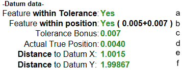 a) Feature within tolerance: Yes/No
-
- Is the hole or shaft within tolerance.
- b) feature within position: Yes / No (Position + Bonus allowance)
-
- Does the position of the center axis of the hole or shaft lie within the target position diameter including the bonus value if applicable.
- c) Tolerance bonus: decimal value / No bonus
-
- Displays the amount of the bonus allowed or No bonus if not applicable.
- d) actual true position: decimal value
-
- displays the actual diameter the center axis of the hole or shaft lies on. This is a deviation from perfect 0 (zero) position.
- - NOTE: (only displayed if Position and compensated height inputs were entered)
-
e) calculated distance from primary datum plane
-
f) calculated distance from secondary datum plane
- - Feature height data results:
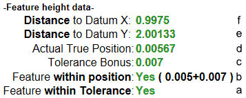 - same as "Datum data" with the exception that the results are displayed in the reverse order.
-
- NOTE: values grayed out (For reference only)
-
- The values are grayed out when a Projected target position was evaluated. These values were used to calculate the projected position . These values are not to be considered when evaluating a projected position and are for reference only.
- - Projected data results:
- a) Projection height
-

- displays the minimum height of the projected position value. This is the same value that was entered in the target feature control frame.
- b) Projection within position: Yes/No
-
- Is the calculated position of the calculated projection within the target position and the bonus value (if applicable).
- c) Projection true position: decimal value
-
- displays the actual diameter the center axis of the projected position lies on. This is a deviation from perfect 0 (zero) position.
- d) Calculated distance from primary datum plane
- e) Calculated distance from secondary datum plane
Further explanation on this subject will be available at later date...